S
Standard Gun Assembly (SGA) & True Trigger Setup Instructions
Step-by-step guides & documentation
SGA Setup Instructions
CONFIGURATION & FITTING
Before starting, ensure that your firearm is safe to use with DryFire and that it is not loaded. Remove any magazine.
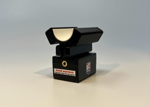
Note: The DryFire SGA is a laser device. When you press the trigger switch the DryFire SGA sends out a short (appx 40ms) pulse of low power invisible infrared laser light which bounces off the wall/screen and is detected by the cameras in the simulator.
The DryFire SGA comes attached to a magnetic Quick Mount Adapter. If you are shooting a 12 or 20-gauge, magnetic mounting is the easiest way of mounting the SGA to your gun. For a .410 or BB gun, use a barrel clamp which is available upon request.
The SGA clips under the barrel of your shotgun, close to the fore-end. Make sure the laser is pointing towards the muzzle.
The supplied wrap-around trigger switch is designed like a tie-wrap, and goes around the trigger blade so the micro switch is under your trigger finger. Fit the trigger switch to your trigger blade and connect the other end of the wire to the SGA.
The Status indicator will flash briefly each time the trigger switch is pressed (or released if configured in Release to Fire mode). If the red LED does not flash when the trigger is pressed, then try changing the battery.
Changing the Battery
The SGA uses a CR2032 coin cell battery. The battery should be replaced if the red LED fails to flash when the trigger switch is pressed.
To change the battery, remove the 4 screws from the bottom of the box, remove the old battery, and replace it with a new one. Take care to not over tighten the screws when replacing the bottom cover piece.
How to Configure a "Release" Trigger
Configuring the SGA for RELEASE TO FIRE Mode
The DryFire SGA comes configured in the Press to Fire mode. To change to Release to Fire mode:
- Remove the 4 screws from the bottom of the box
- Move the small shorting link (Note: link color may vary) so that it connects across the 2 pins.
- Plug your trigger switch in and test that you have configured the SGA correctly.
- The red LED should now flash when you release the trigger switch.

True Trigger Setup Instructions
INSTALLATION & FITTING
❗️ PLEASE READ ❗️
Please follow the fitting instructions carefully.
1. Do not put the operating arm hard up against the trigger blade. The operating arm rotates very slightly (about 1.5mm) and trying to force it beyond this limit of movement will damage the switch. When installed correctly the switch should operate during the last 1.0mm/1.5mm of trigger movement. You can feel and perhaps hear, the internal switch operating as the operating arm is pressed.
2. The instructions allow you to set up for right-hand or left-hand use.
3. After the first time, setting up your True Trigger should take only a few seconds: fit to guard, slide to the correct location, lock in place.
True Trigger Fitting Instructions:
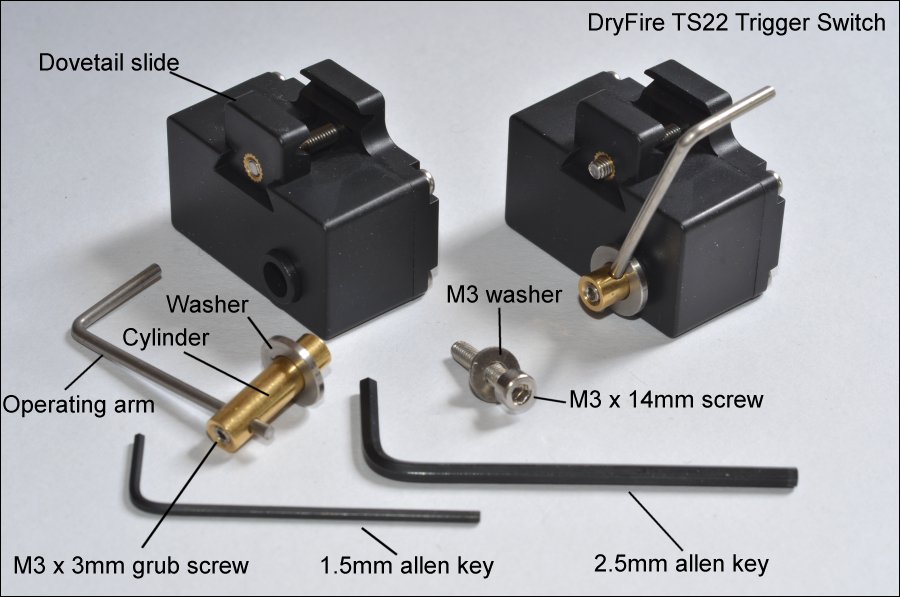
1. Use the 2.5mm Allen key to remove the operating arm and brass cylinder by undoing the M4 14mm cap head hex screw. Don't lose the washers!
2. Use the 2.5mm Allen key to slacken off the M3 18mm cap head hex screw that holds the dovetail slide in place. Don't remove the screw entirely.
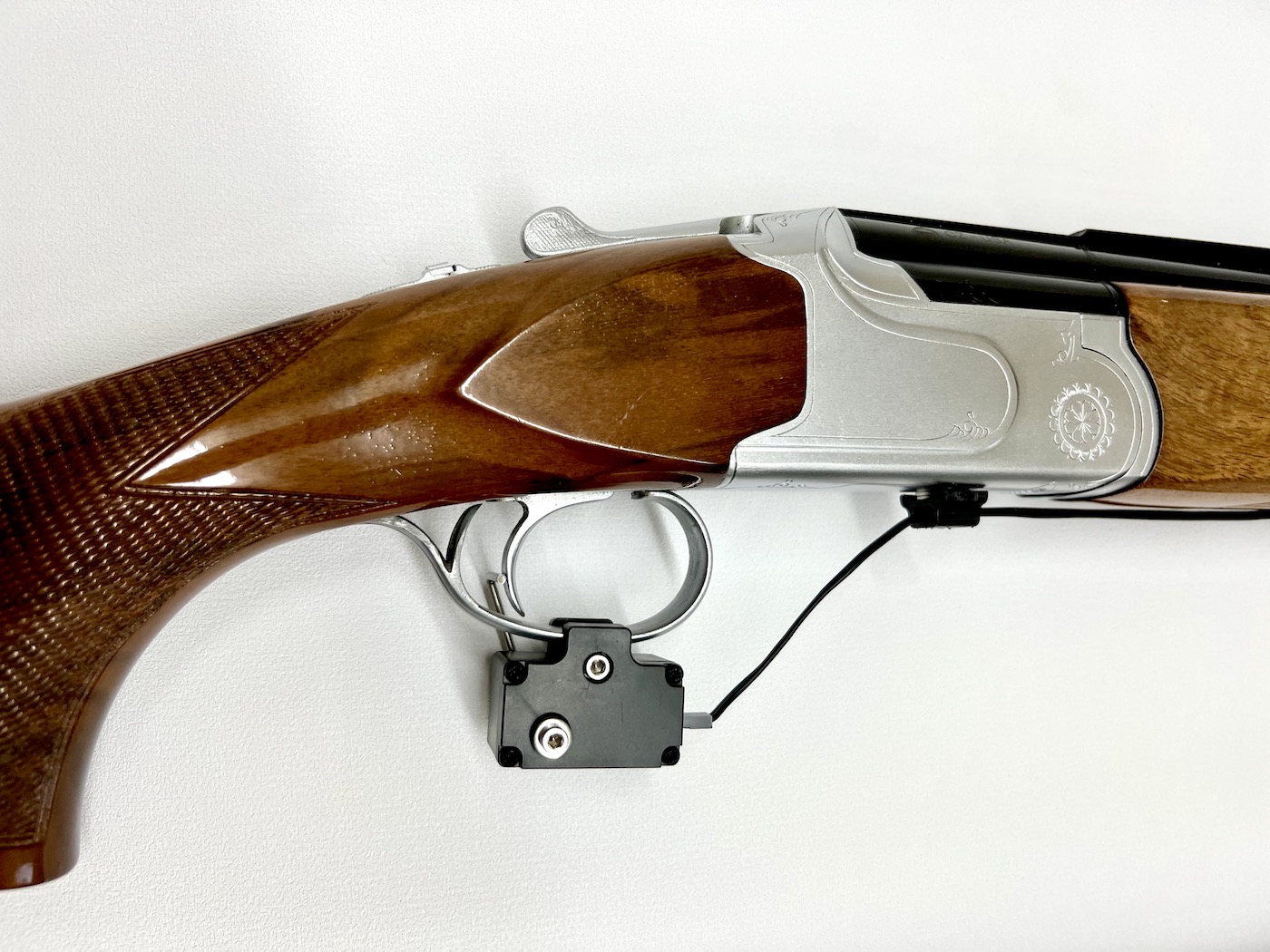
3. Fit the body of the switch to the trigger guard. The edges of the guard will fit into the horizontal slots in the dovetail slide and body. The switch should be under the center of the guard – see the photo above. Don't over-tighten – firm but not tight is correct!
4. Insert the brass cylinder (with operating arm and washer) into the switch body (with the top of the operating arm behind the trigger blade) and hold it in place using the M3 14mm cap head hex screw. Don't tighten the screw at this stage.
5. The cylinder should be inserted into the side opposite to where your trigger finger will go so the operating arm does not interfere with your trigger pull.
6. Adjust the position of the operating arm so the horizontal top rests where the back of the trigger blade will be when a shot is taken. If necessary adjust the length of the operating arm by slackening off the M3 grub screw using the 1.5mm Allen key.
7. When everything is in place, tighten up the M3 14mm screw holding the cylinder in place. Don't over-tighten – firm but not tight is correct!
8. From now on you should never have to adjust the length of the operating arm. Simply slacken off the M3 18mm screw for the dovetail slide for it to open up enough for you to remove and refit the switch. The next time you're fitting the switch, adjustments to the location of the top of the operating arm can be made by sliding the switch backward or forward on the trigger guard before fixing it in place.
10. Connect the trigger switch to the Standard Gun Assembly (SGA) using the 2-way, female-to-female cable.
11. Switch on the SGA and press the trigger. You should see the red LED flash on the SGA.